Calcination is the last step in the Bayer process, and is sometimes considered a standalone technology. However, its integration with the Bayer process itself is critical, subject to defined soda requirements, reduction of moisture from hydrate filtration areas, a source of heat recovery and, most importantly, the correct understanding of hydrate properties and correlation with product breakage (the latter a critical point to the downstream smelting process).
Jun 30, 2019
Generation 5 Calciner
We introduced our calcination technology to the alumina industry in 1970, and since then it has gone through several development stages, resulting in the state-of-the-art technology that Metso Outotec has provided to recently commissioned alumina refineries. In this article, you will learn about them and how we have significantly managed to increase capacity and reduce the environmental footprint of alumina calcination.
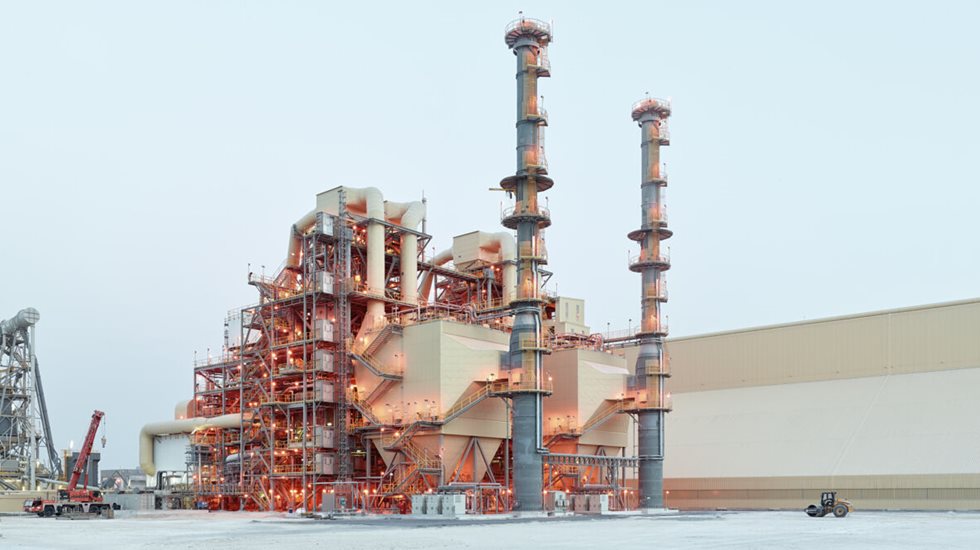

Figure 1: Block Diagram of the Bayer Process
Since its inception, the Bayer process calcination technology has progressively changed throughout the 20th century. The first devices were wet rotary kilns, crude devices similar to those deployed in the cement industry at the turn of the 19th century, which consumed a lot of energy (up to 8 GJ per ton of calcined alumina), having to evaporate exorbitant amounts of water, no pre-heating nor recuperative cooling stages. Progressively, as recuperative heating stages were introduced, such as the example in Figure 2, a few exemplar operations have claimed to achieve as low as 4 GJ per ton.
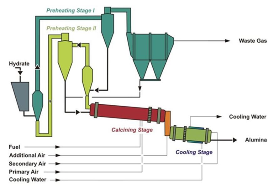
Figure 2: Schematic of a Rotary kiln calciner with preheating stages
With continuous pressure to reduce fuel consumption whilst maintaining comparable product quality, fluidized beds were being piloted as early as the late 1950’s, and the first industrial units appearing in the early 1970’s just as the Middle East oil crisis reached its peak. This was followed by wide spread industrial retrofits compounded by green- and brownfield alumina refineries capacity additions resulting in total abandon of kiln technology. The inflection, as illustrated in Figure 3, shows how the best operating practices witnessed a clear change in energy consumption during that critical period.
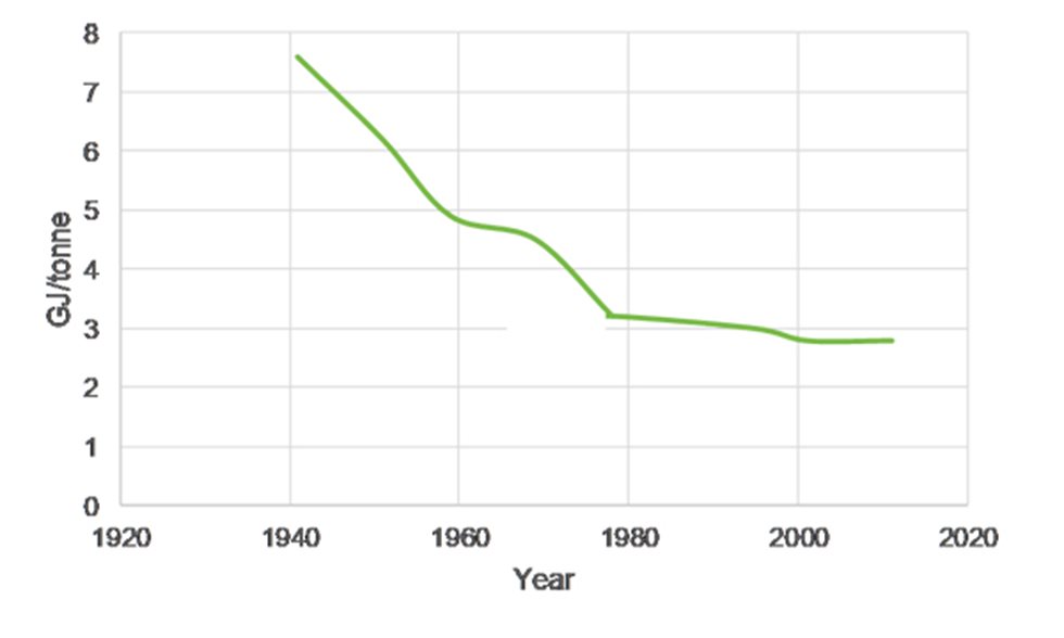
Figure 3: Best operating practice calcination energy consumption
With continuous pressure to reduce fuel consumption whilst maintaining comparable product quality, fluidized beds were being piloted as early as the late 1950’s, and the first industrial units appearing in the early 1970’s just as the Middle East oil crisis reached its peak. This was followed by wide spread industrial retrofits compounded by green- and brownfield alumina refineries capacity additions resulting in total abandon of kiln technology. The inflection, as illustrated in Figure 3, shows how the best operating practices witnessed a clear change in energy consumption during that critical period.
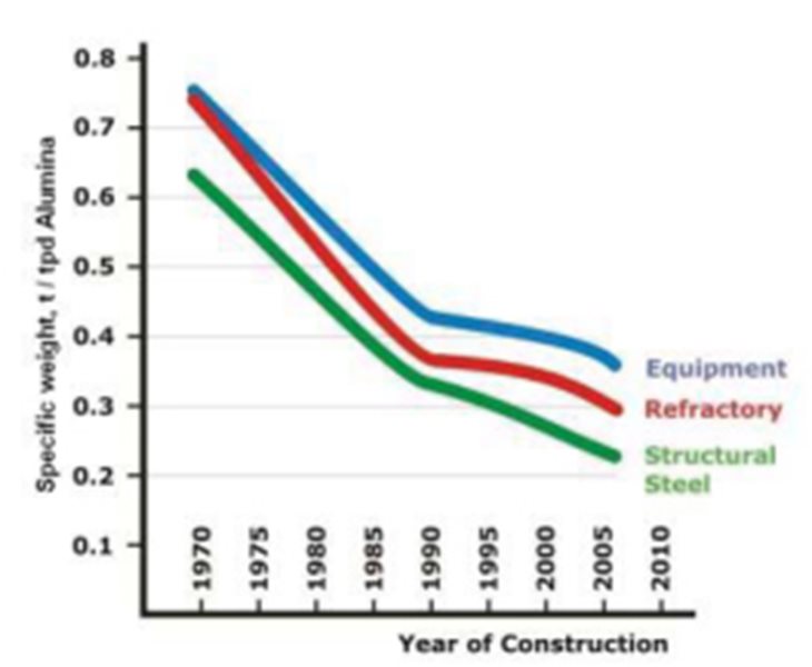
Figure 4: Specific weight profile timeline for the circulating fluid bed calciners
With continuous pressure to reduce fuel consumption whilst maintaining comparable product quality, fluidized beds were being piloted as early as the late 1950’s, and the first industrial units appearing in the early 1970’s just as the Middle East oil crisis reached its peak. This was followed by wide spread industrial retrofits compounded by green- and brownfield alumina refineries capacity additions resulting in total abandon of kiln technology. The inflection, as illustrated in Figure 3, shows how the best operating practices witnessed a clear change in energy consumption during that critical period.
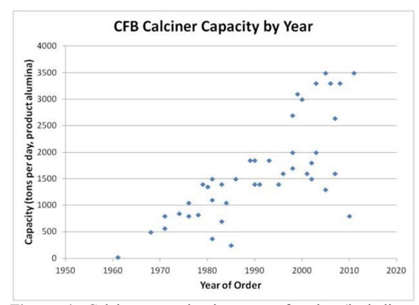
Figure 5: CFB calciner capacity year by year
The Generation 2 Calciner, installed in the first two lines in Nalco, India, as well as Bauxlium, Worsley lines 1 and 2, Giuzhou, Shandong, Nikolaev lines 1-4, and Alunorte A and B (1980s- 1990s), shows a clear decoupling between the first pre-heating stage and the stage 2 cyclone by means of pneumatic duct. In addition, the electrostatic precipitator was designed to handle full hydrate throughput, this resulted in a change in layout with key equipment such as lowering the ESP and the 2nd pre-heating stage closer to the ground level, leading to a reduction in relative structural requirements.
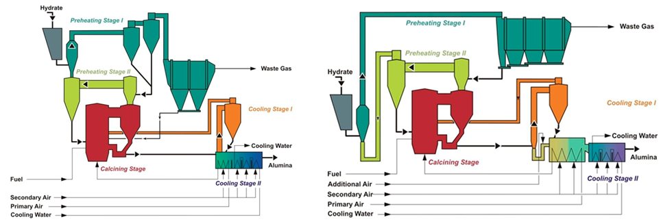
Figures 6 & 7: Generation 1 & Generation 2 Calciners
The Generation 3 and 4 Calciners in Figure 8 and Figure 9 have witnessed the introduction of the 2nd cooling stage and progression towards an integrated fluid bed cooler to a single piece of equipment with common walls and multiple chambers. Examples of such plants were Nalco line C, Worsley 5, Shandong and Giuzhou II, Nikolaev 5, Hindalco Muri, Gove K5-7 and Alunorte C, D, E, F and G (2000s).
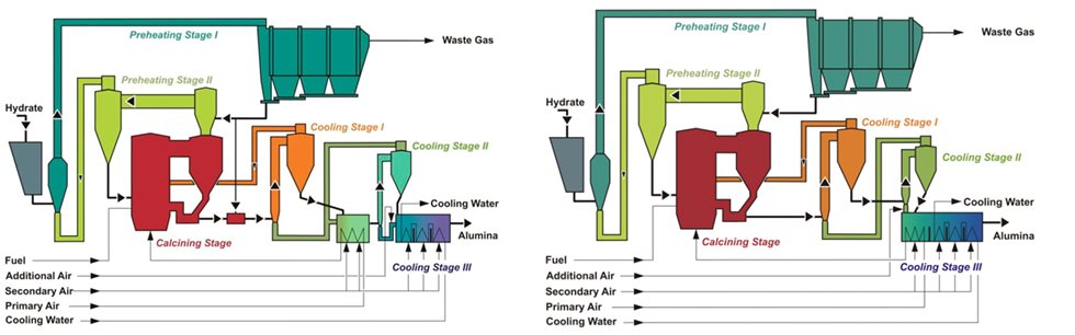
Figures 8 & 9: Generation 3 & Generation 4 Calciners
The design finally culminated with the development of the Generation 5 Calciner (Figure 10) with the clear intent to reduce overall plant weight, such as implementation of pre-separation stage prior to the electrostatic precipitator, and replacement of the airlift altogether with a pneumatic transport system. This generation of technology has been successfully implemented on three sites with fives units currently in operation.
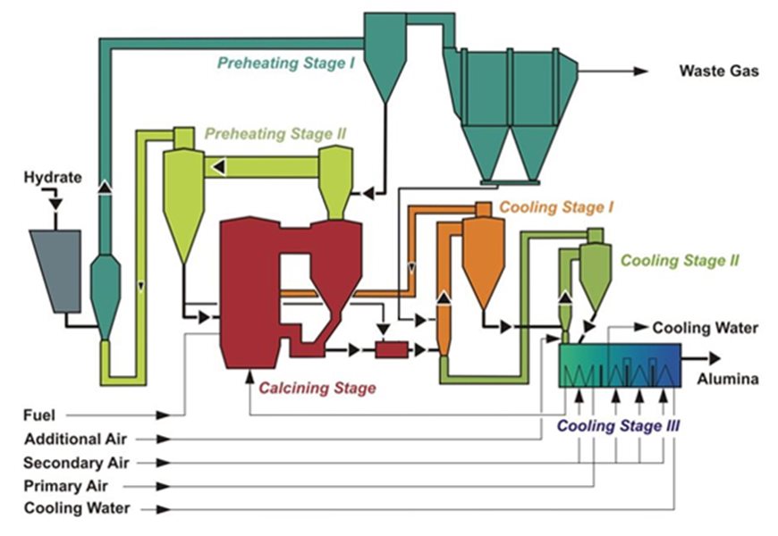
Figure 10: Generation 5 Calciner
Although the results in reduction of specific weight have been gradually explained, the corresponding and progressive reduction in specific fuel consumption is also of worthy note.
Figure 11 is a testament to this showing how this specific unit operation has witnessed a 50% reduction in specific energy consumption albeit with wholesale changes in the technological approach from the inception of the Bayer process to today.
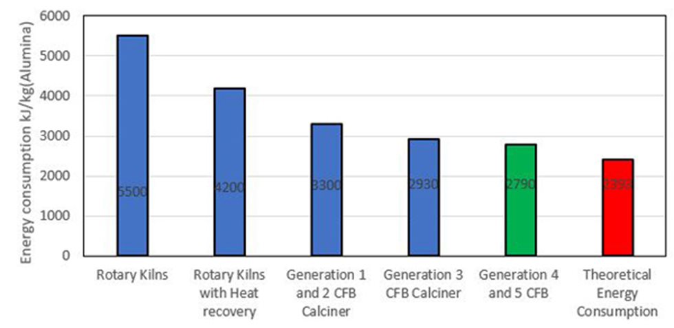
Figure 11: Progressive drop in specific energy consumption versus calciner technology
Most recently, with the introduction of calcination optimizers (advanced process control) that can be installed on existing plants, the energy consumption and environmental footprint of existing calciners can be reduced further. More on that in newsletters to come.
Outotec is a world leader in alumina refinery technologies, with a particular focus on calcination and hydrate filtration, tube digestion (HOT JV), settler washers, red mud filtration and security filtration.
References: Klett et al., Alumina Calcination: A mature Technology under review from a supplier perspective, TMS, Light Metals, 2015.