Metso Insights Blog Mining and metals blog Flotation columns getting the most from fine ores
Mining Metals refining
Oct 16, 2017

Flotation columns: getting the most from fine ores

The first flotation machine design to use the column concept was developed by Town and Flynn in 1919 – a column was used with an injection of air in the bottom by a porous plate. In subsequent decades, this type of device was substituted by the impeller-type flotation machines in mineral processing plants due to the absence of effective and reliable air spargers for fine bubble generation and the lack of automatic control systems on the early columns (Rubinstein, 1995). Column flotation devices were re-introduced for mineral processing by Boutin and Wheeler in Canada in 1967, when wash water addition to the froth was used to eliminate entrainment of hydrophilic materials to the float product. By the late-1980s column flotation had become a proven industrial technology in the mineral industry.
Outotec ColumnCells
Figure 1. Outotec ColumnCells.

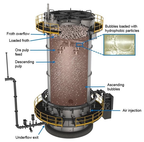
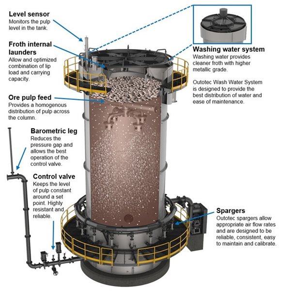
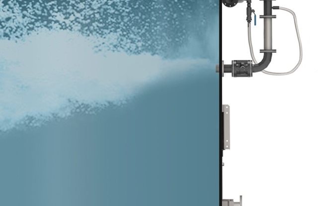
Flotation columns comprise a tall tank, in which the separation between froth and pulp occurs, an aeration system, a pulp level control system, a wash water system, a discharge barometric leg and a set of control instruments, besides pipe connections for feed, concentrate and tailings. Figure 1 illustrates a typical column.

Process description and technological phenomena of a column

The column is fed with ore pulp in its upper third portion and, at the lower section, air is injected at high velocities. This causes the pulp to flow down against a swarm of rising air bubbles. This counter-current flow promotes the suspension of particles in the pulp. In addition, the energetic injection of air provides for the generation of small bubbles and promotes the contact of these bubbles with the ore, leading to the collection of hydrophobic particles.

The loaded bubbles ascend and form a thick froth layer at the column top, which is favored by the shape of the device, which has a smaller diameter than its height. Just over the column top, a system gently distributes water over the froth, which washes most of the entrained hydrophilic material back to the pulp. The froth thickness and this washing process enable a higher enrichment of ore in the froth, improving the quality of concentration and the recovery. The froth that is rich in hydrophobic material is discharged in the launders. In direct flotation, this froth corresponds to the concentrate. Hydrophilic particles flow down and leave the column through a barometric leg, which includes a level control system. This corresponds to the underflow and, in the case of direct flotation, to the tailings. Figure 2 illustrates the flotation process within a column.

Flotation process within a column
Figure 2. Flotation process within a column.

Typically, columns are suitable for ores with a particle size bellow 150 µm. Larger particles tend to be too heavy to be kept in suspension. This size limit may vary depending on the ore density. Lighter ores, such as phosphate, are amenable to column flotation at larger particle sizes.

Typical limit of particle size
Figure 3. Typical limit of particle size for application of columns and mechanical cell for most minerals.

Physically, column flotation is controlled through adjustments in the pulp/froth level, in the flow rate and pressure of air, and in the wash water flow. Besides these physical aspects, the reagent scheme can also be changed to achieve the desired performance. The correct combination of all these factors for a specific ore provides the optimized concentration of minerals.

Features of a column

Since columns do not have mechanical agitation, their energy consumption is optimal. This feature makes columns a very good option for processing fine ores with the aim of obtaining froths rich in hydrophobic material. Figure 4 presents the main features of a column.

Main features of a flotation column
Figure 4. Main features of a flotation column.

Aeration – the most essential aspect of columns

The aeration system is the most essential part of columns. Columns perform best if:

  • The air flow rate is appropriate for the ore and for the column
  • The bubble size is small
  • The air is well distributed all over the column

Several of the first industrial columns in the 1980s presented inconsistent results due to the use of rudimentary aerators, most of them based on perforated plates or tubes. From the 1990s on, there were several developments in aeration systems aiming at avoiding plugging, wear and process interruption.

The latest Outotec SonicSparger™ represents the state of the art in sparging technology and were developed to achieve the best flotation performance. They are safe, consistent and reliable, easy to maintain and do not require the interruption of column operation for inspection or maintenance. There are two types of SonicSparger system available: SonicSparger Vent and SonicSparger Jet. Both types can be used to modernize existing columns to improve column flotation results.

{{zoomedImageIndex + 1}}/2
{{ captions[zoomedImageIndex] }}

Application of columns

In reverse flotation, columns have been used to remove fine gangue in a selective way, guaranteeing a high recovery of the main mineral in the underflow. In iron ore processing, for instance, they are commonly used to remove silica.

In direct flotation, columns have been used mainly for cleaner stages due to their capacity for generating high-grade froths with fine material. The most common configuration involves a rougher with mechanical cells and a cleaner with columns, after regrinding the intermediate concentrates. This type of flowsheet aims at minimizing grinding costs. Mechanical cells are used with a coarse feed, with a particle size that is just enough to provide high recovery in flotation. This stage generates an intermediate and unliberated concentrate, typically with a significantly lower mass than the original feed. Then only this rougher concentrate is reground, reducing the investment in grinding. The reground product is further concentrated in the columns, which are more appropriate for fine material.

This configuration may change completely depending on the ore type, particle size and product demands. Once the ore particle size is appropriate for column flotation, circuits may vary from having all cells as mechanical cells to all of them as columns, as well as various combinations of both. Figure 4 and 5 present some examples of real circuits.

Process with columns in cleaner stages
Figure 7. Process with columns in cleaner stages.

With column flotation in its product portfolio, Outotec can provide a complete and optimized package of flotation solutions. The best option or combination of cells for a specific project can be defined by a technical and economical evaluation.

In the next issue of Minerva, we discuss the considerations and benefits of different sparger systems for column cells.

References

Rubinstein, J.B., 1995. Column Flotation: Processes, Designs, and Practices. Gordon and Breach Science Publishers, Basel, Switzerland; Langhorne, PA.

Process with columns in rougher and cleaner stages
Figure 8. Process with columns in rougher and cleaner stages.
Mining Metals refining